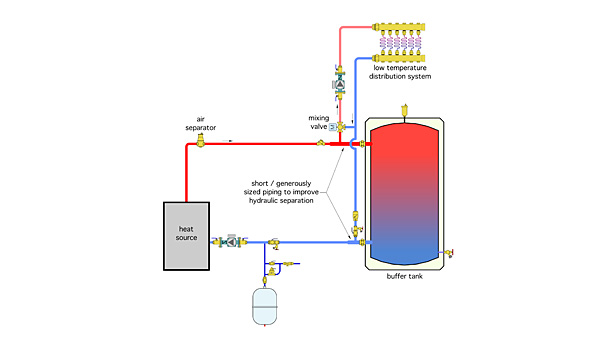
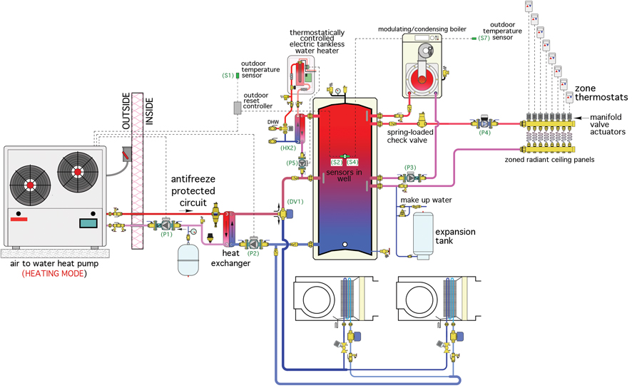
Chilled water buffer tank piping diagram findscotland co uk may 1st 2018 chilled water buffer tank piping diagram ebooks chilled water buffer tank piping diagram is available on pdf epub and doc format you can directly download and save in in to your device alternate methods to pipe a buffer tank 2014 10 22.
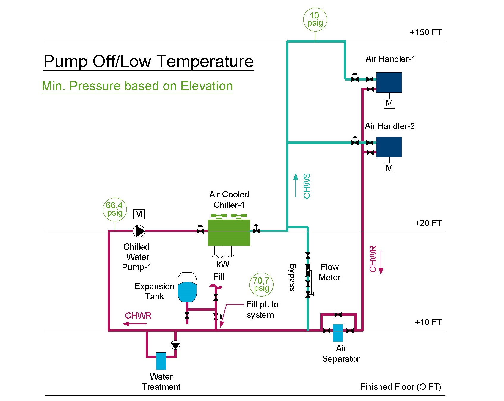
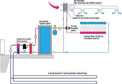
Schematic chilled water buffer tank piping diagram.
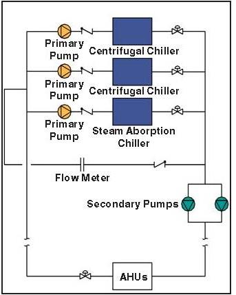
Chilled water schematic and condenser water schematics.
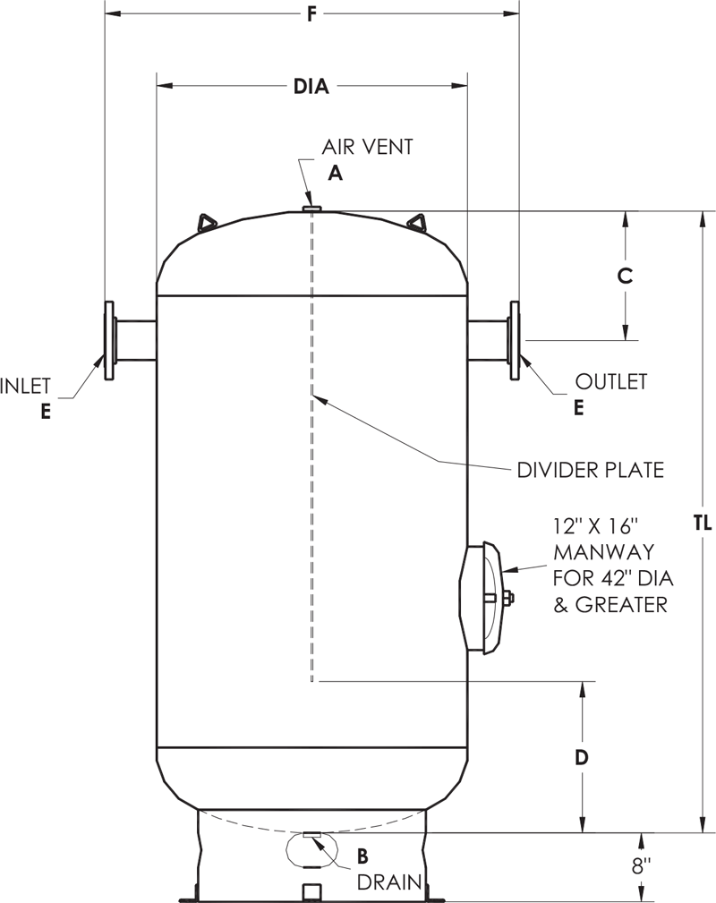
This ensures proper water circulation and full use of the tank volume.
As the system water enters the tank it is forced up and over the baffle before dropping back down to exit the tank.
System flow below chiller min flow 250 gpm variable primary flow at 25 system load two way valves control capacity by varying flow of water in coils per chiller system load 50 tons 176kw 50tons 176 kw primary bypass flow 250 gpm 95 l s 150 gpm 9 5 l s delta t 12 of 6 7 oc 100 gpm 44 ºf 6 3 l s 6 7 ºc 56 ºf 13 3 ºc 150.
The unit is designed with an internal baffle.
How is the water circulated inside the tank.
Cemline chilled water buffer tanks cwb are designed to be used with chillers which do not have water volumes of sufficient size in relation to the chiller.
Po box 55 cheswick pa 15024 phone 724 274 5430 fax 724 274 5448.


